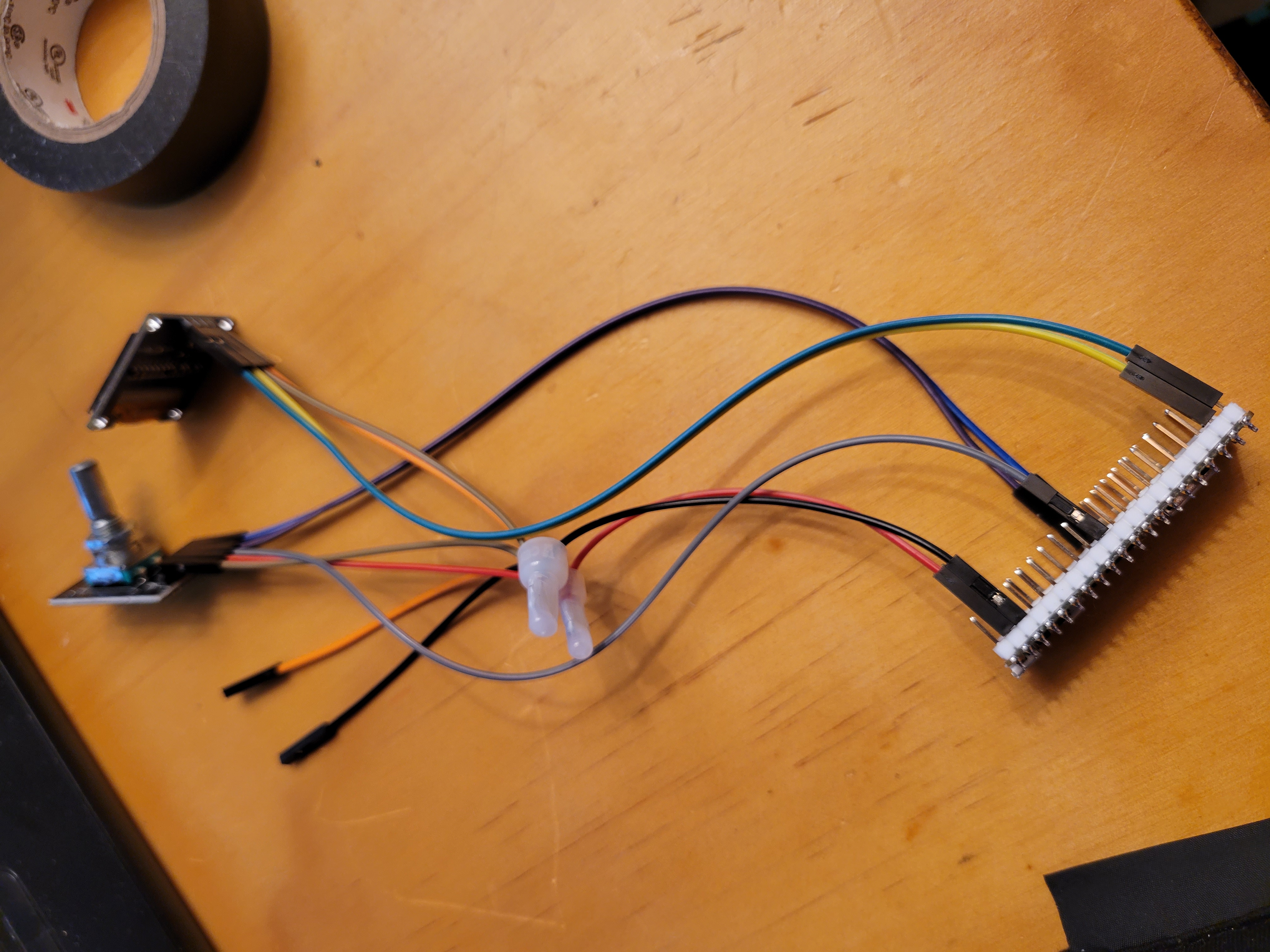
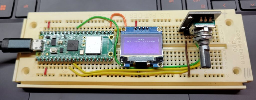
This is documentation of building the 3d printed case with a full setup. An Amazon shopping list of all components used in the construction are here:
https://www.amazon.com/hz/wishlist/ls/BSNG6DAUWYA3?ref_=wl_share
Step 1:
Setup your Pico with the latest version of micropython. Be sure to load the correct file depending on whether you are using a Pico or a Pico W.
https://projects.raspberrypi.org/en/projects/getting-started-with-the-pico
You may also want to do Step 7 now and load the programs onto the Pico chip at this point. They can be found at https://github.com/jamesreneau/picohhg
Step 2:
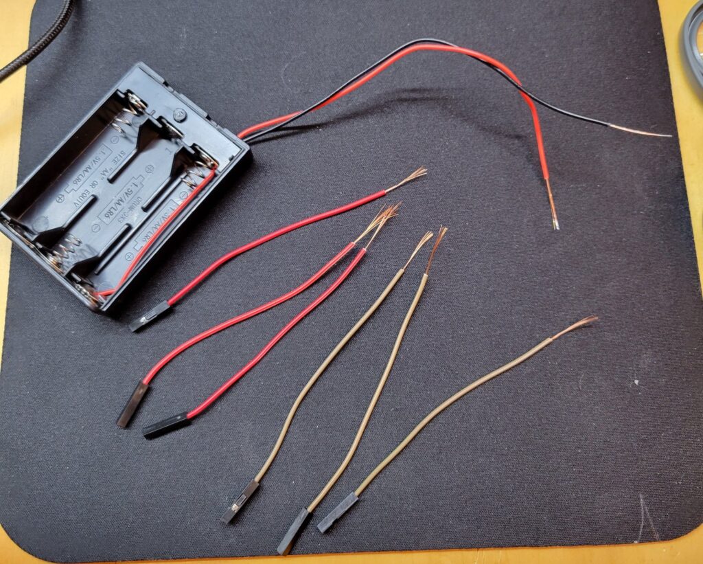
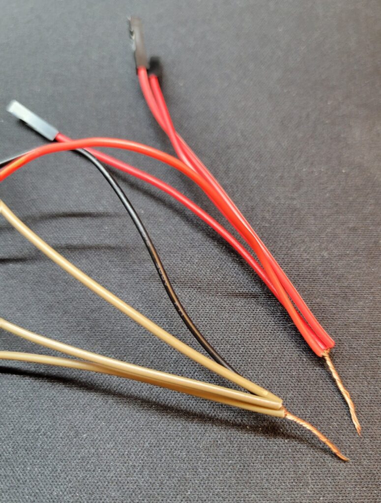
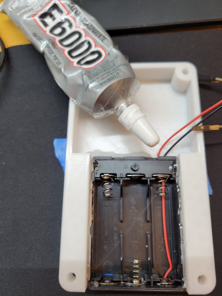
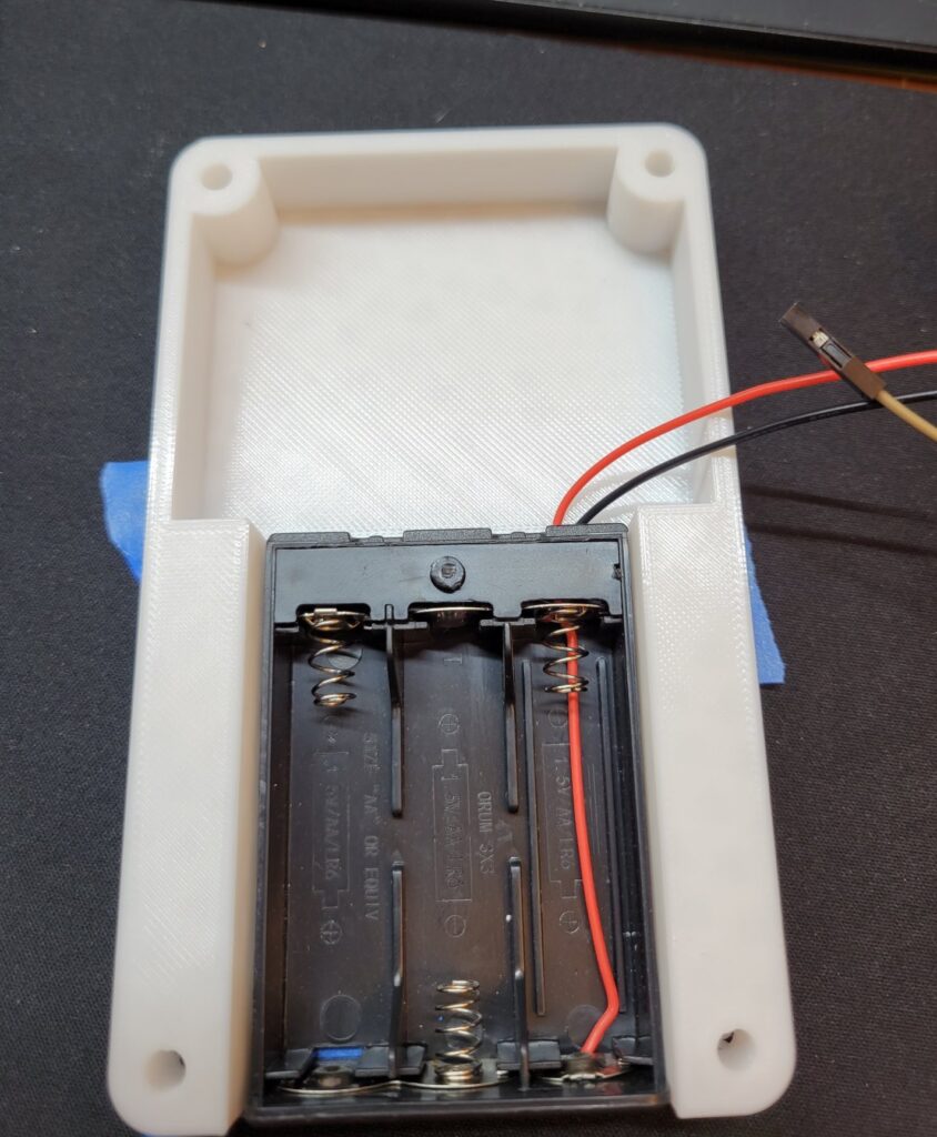
Cut 2 red and 2 black Dupont wires in half. Strip and add to the leads from the battery holder. I used small wire-nuts but you can solder and shrink wrap. You should have 3 red leads and 3 black leads. (In the pictures I used brown because it is what I had)
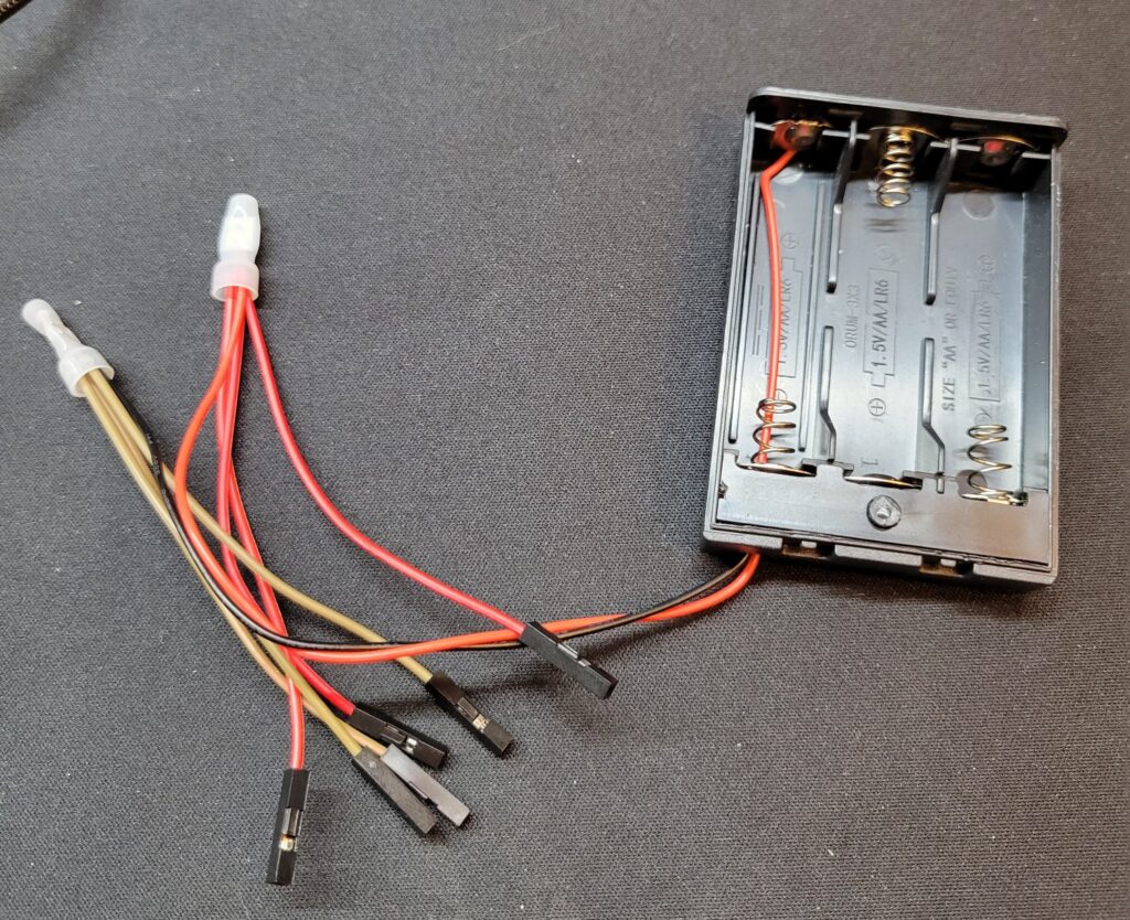
Step 3:
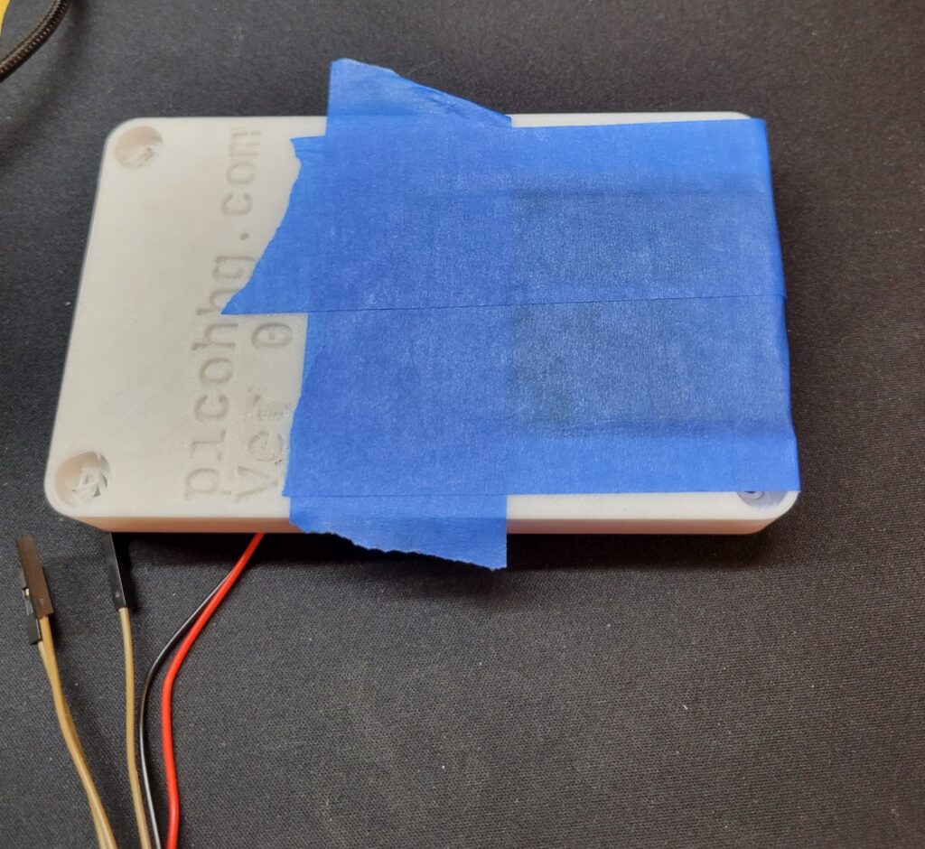
Glue battery holder on bottom half of the case and glue the OLED to the top half of case. I suggest using a glue like E6000 or some other flexible fast drying glue. I used pieces of blue painter tape to hold the parts in place while the glue sets. Let Dry.
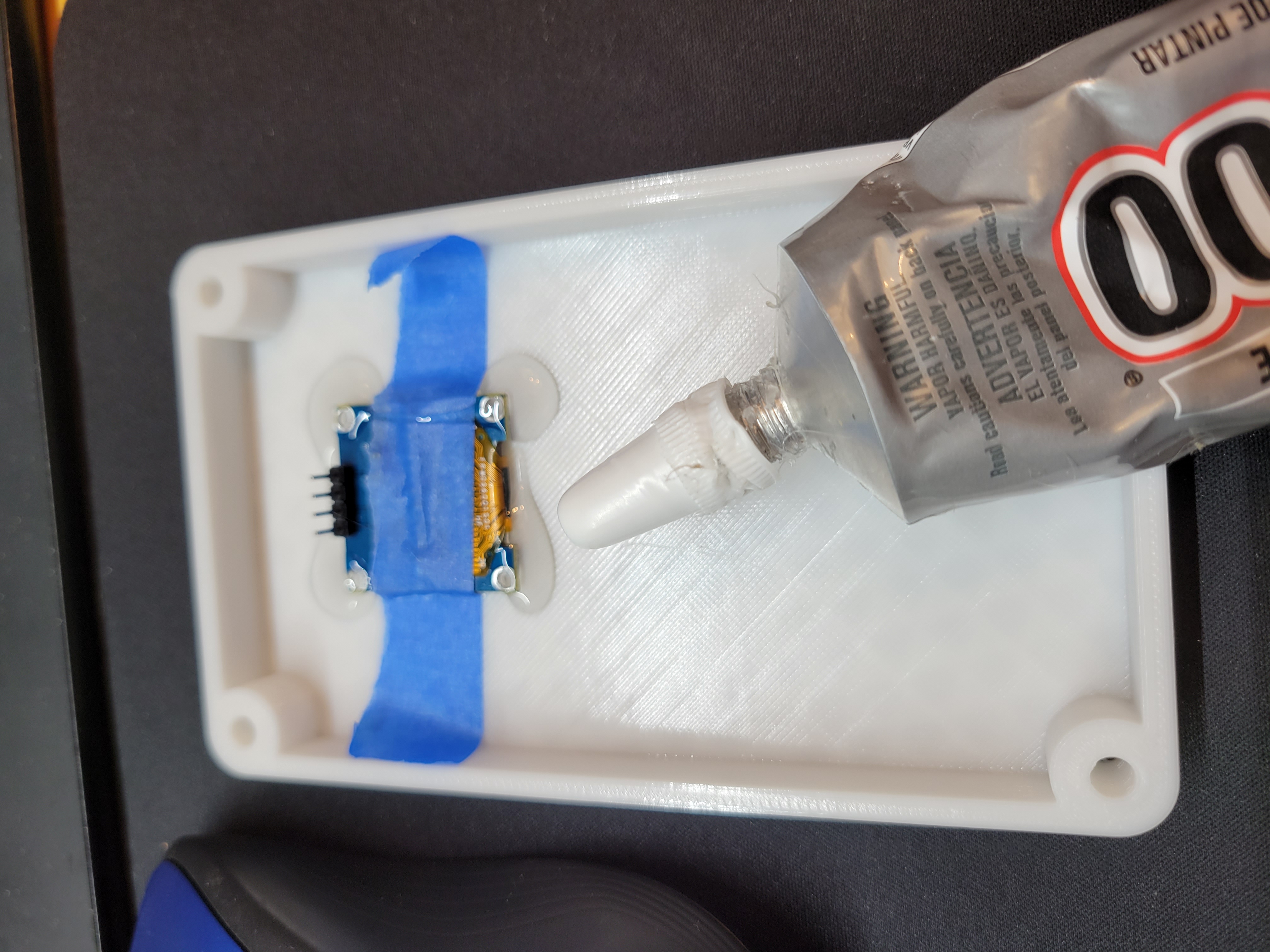
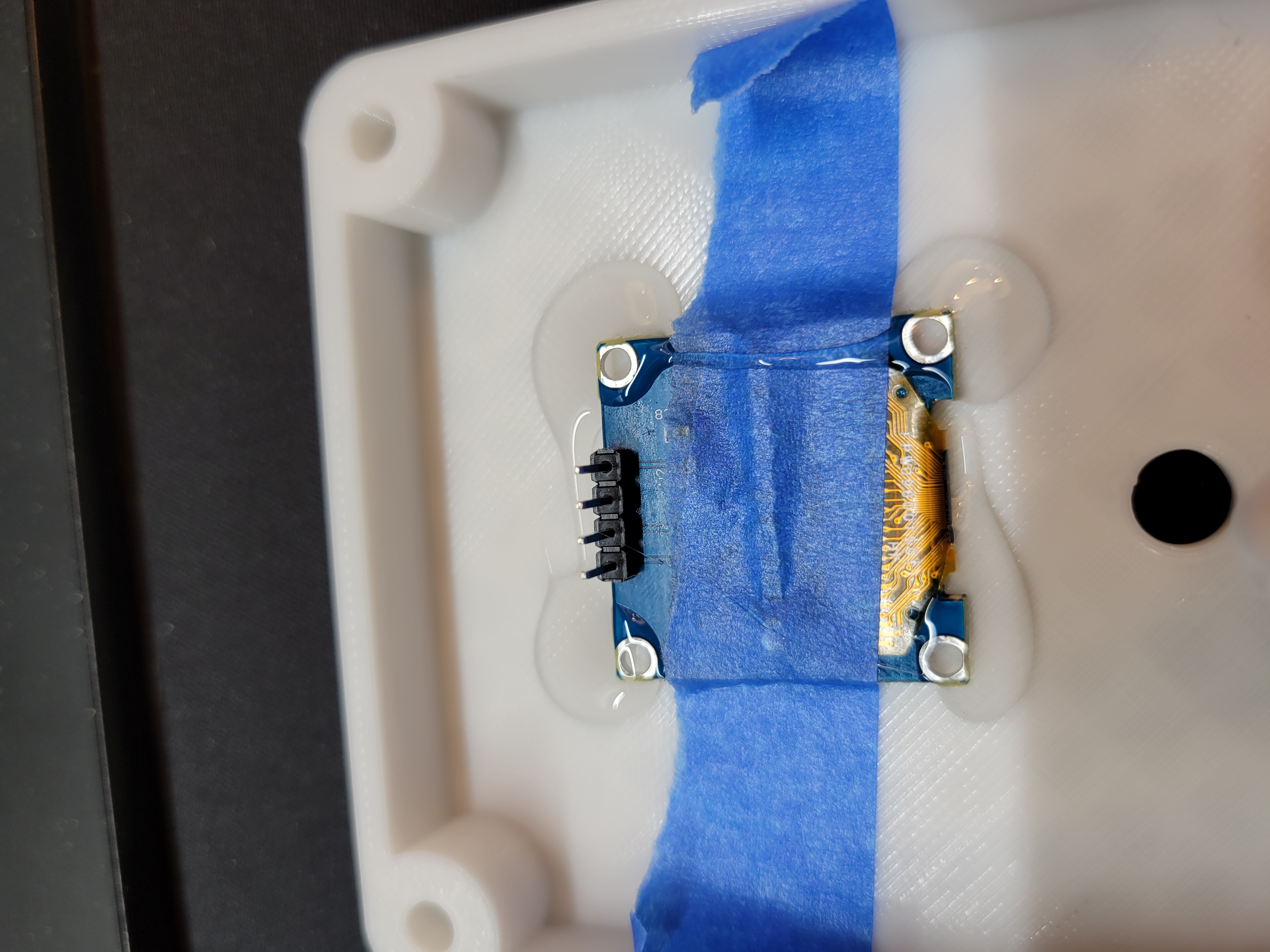
Step 4:
Install rotary encoder in hole on top of case.
Step 5:
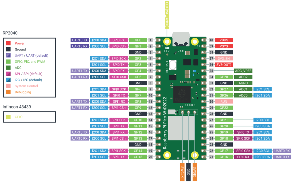
With the OLED, wire the SCL to GP17 (Pin 22) and SDA to GP16 (Pin 21). Also wire VCC to a red lead from the battery and GND to a black battery lead.
Step 6:
With the Rotary encoder, wire CLK to GP7 (Pin 10), DAT to GP6 (Pin 9), and SW to GP26 (Pin 31). Also wire VCC to a red lead from the battery and GND to a black battery lead.
Step 7:
Connect to computer using a USB cable and install the Programs. I use “ampy” and “thonny”. The MicroPython source and how to load the PicoHHG can be found at https://github.com/jamesreneau/picohhg
Step 8:
Connect to Pico to the battery leads. VSIS (Pin 39) to a red lead from the battery and GND (Pin 38) to a black battery lead.
Step 9:
Stuff into case and use 4 #6 screws and nuts (or fastener of your choice) to close the case. You may want to protect the back side of the OLED and rotary switch with black tape so that nothing can rub and short. You may also want to protect the boot switch so that it can’t be pressed when the case is closed (I used a little piece of a wire nut and taped it over the switch).
Step 10:
Turn on – Have fun.
Earlier Prototypes
